CFD Simulation of Immersion Cooling
Background
Previous work by NSES, LLC focused on air cooling a HPC computing platform. The customer’s preferred approach followed the traditional concept where each server rack employs a multitude of fans that drive cooled, ambient air past intricate heat sinks mounted to electrical components with high power dissipation. Aside from deafening fan noise, the heat transfer from convective air cooling tends to taper off at high flowrates thereby limiting the achievable power dissipation for each server rack. Alternatively, liquid cooling of individual components (common with high-end gaming rigs) is not always suitable for server hardware because the sheer number of high- powered components scattered across the mother board would lead to overly complicated and failure- prone coolant circuits. The most elegant and best performing solution for many server applications appears to be immersion cooling where the entire electronics assembly is placed into a bath of dielectric fluid (see Figure 1). Early applications of this cooling concept to computer systems date back to the 1960s by IBM (US patent US3406244A) and 1980s by Cray Research (US patent US4590538A). Both patents mention the advantages of two-phase cooling which necessitates dielectric fluids (typically fluorocarbons) with boiling temperatures sufficiently below the maximum junction temperature of the electronics components to be cooled.

Figure 1: Bath tank with server hardware (Image Source)

Figure 2: Vapor bubbles during operation (Image Source)
Advantages
Previous work by NSES, LLC focused on air cooling a HPC computing platform (see here). The customer’s preferred approach followed the traditional concept where each server rack employs a multitude of fans that drive cooled, ambient air past intricate heat sinks mounted to electrical components with high power dissipation. Aside from deafening fan noise, the heat transfer from convective air cooling tends to taper off at high flowrates thereby limiting the achievable power dissipation for each server rack. Alternatively, liquid cooling of individual components (common with high-end gaming rigs) is not always suitable for server hardware because the sheer number of high- powered components scattered across the mother board would lead to overly complicated and failure- prone coolant circuits. The most elegant and best performing solution for many server applications appears to be immersion cooling where the entire electronics assembly is placed into a bath of dielectric fluid (see Figure 1). Early applications of this cooling concept to computer systems date back to the 1960s by IBM (US patent US3406244A) and 1980s by Cray Research (US patent US4590538A). Both patents mention the advantages of two-phase cooling which necessitates dielectric fluids (typically fluorocarbons) with boiling temperatures sufficiently below the maximum junction temperature of the electronics components to be cooled.
Challenges
Obviously, there are limits to how much heat can be removed from surfaces using buoyancy-driven, two-phase immersion cooling. High bubble densities (= vapor volume fraction) near the surfaces will eventually turn into a continuous vapor film that will drastically hamper the heat transfer. The maximum achievable heat flux is called the ‘critical heat flux’. Also, simply immersing a server motherboard designed for air cooling into a tank of dielectric fluid may not realize the full potential of immersion cooling. Heat sink geometries should be designed specifically for immersion cooling or the full cooling potential may not be realized. More on this is planned for future discussions on this topic.
Fluids
An important enabler of this technology is the availability of engineered coolants that are environmentally safe. This allows for immersion cooling at ambient temperatures and without the need for hermetically sealed containers or special handling of the coolant.
The key coolant properties from a heat transfer perspective are high thermal conductivity, high heat capacity and, most importantly for two-phase cooling, a boiling point sufficiently below the maximum junction temperature of the component to be cooled.
It should also be noted that both the conductivity and heat capacity of most dielectric fluids is usually lower than those of water. But water comes with its own set of challenges that make it less suitable for immersion cooling. There have been attempts to use water in conjunction with conformal coatings to protect electronic assemblies from short-circuiting, but these coatings invariably increase the thermal resistance between junction and fluid which partially negates the more favorable thermal transport properties of water.
The immersion cooling simulation discussed here uses the material properties of HFE-7100, a Hydrofluoroether which is available from 3M under the tradename Novec 7100 (see Figure 3).
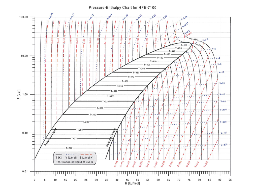
Figure 3: Phase diagram for HFE-7100 (3M Novec-7100) provided by L. Stang/B. Wilson from 3M.
The boiling point of HFE-7100 at atmospheric pressure is at 61°C (334 K) which makes it a suitable candidate for a large range of immersion cooling applications though dielectric fluids with both lower and higher boiling temperatures are available (link to 3M website).
Performance Demo
To better assess the performance potential of a technology it is often expedient to simulate a test case that embodies all the salient feature of a potential application without being burdened by unnecessary complexity. This allows for a quantitative comparison with competing technologies and the potential experimental validation of a test case in hardware. To that end, a test case was constructed (see Figure 4) for the purpose of evaluating the cooling performance for an electronics assembly consisting of a chip (e.g. FPGA in BGA package), a PCB (FR4 with 2 oz CU) and a generic Aluminum heat sink. Since the objective of this study focused on the heat transfer to the fluid and not on the peak junction temperature of the chip, all other thermal resistances (BGA package, thermal pad) were ignored.
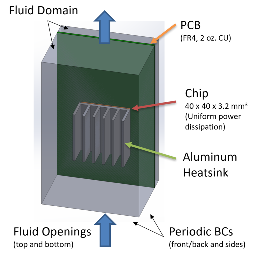
Figure 4: Configuration of performance demo. Fluid enters the domain primarily from the bottom and exits at the top. In a server application, multiple boards are stacked front-to-back (see Fig. 1), hence the use of periodic BCs.
CFD Simulation
A transient CFD simulation of this configuration was performed using Ansys CFX:
- Initial conditions: fluid temperature at 60°C, no vapor, chip/heatsink/PCB temperature at 65°C
- Boundary conditions: fluid temperature (influx) at 60°C, no vapor, atmospheric pressure
Since the boiling point for HFE-7100 is 61°C, the hot component surfaces heat up the fluid and initiate nucleate boiling at (and near) the walls. The simulation uses the RPI wall boiling model that governs the nature of evaporation at the wall. There are many parameters defining the wall boiling model that are application specific (e.g. surface material/roughness/texture directly affect the starting point of actual boiling). For best accuracy, it is generally recommended to calibrate the model parameters based on experimental data. This greatly enhances the predictive qualities of the model when used for optimizing a new design. Figure 5 shows a video clip (click to play) starting with the warm-up phase and initial vapor formation up to stationary boiling. Initially, a large quantity of vapor collects above the heat sink that starts to rise slowly but then accelerates the fluid toward the upper domain boundary. This effect is also visible in the development of the velocity field (see video clip in Figure 8).
Figure 5: Visualization of vapor rising off heatsink.
The vapor volume fraction directly adjacent to one of the fins (see video clip in Figure 6) suggests discrete slugs of bubbles rising intermittently along the surface at fairly regular intervals. Although plausible, this behavior may be an artifact of the chosen parameter set defining the RPI wall boiling model and would need to be validated against experimental data.
Figure 6: Vapor formation adjacent to heatsink fin.
It should also be pointed out that a steady-state simulation cannot resolve the intermittent nature of bubble movement seen in Figure 6 but instead predicts a continuous bubble density along the walls that results in an average wall heat flux (see Figure 7). The magnitude of the wall heat flux is very similar for both cases.
Figure 7: Difference between smooth (steady-state) and discrete (transient) bubble concentrations.
Figure 8 shows the influence of the rising vapor bubbles on the flow field. It is clear that the far-field is minimally affected by this buoyancy driven flow. In fact, even the flow in between the fins of the heat sink is quite weak but is becoming stronger toward the upper part of the domain suggesting that the heat transfer is aided both by phase change and enhanced convective heat transfer.
Figure 8: Buoyancy-driven flow field from initial vapor formation to steady-state flow.
Performance Relative to Passive Air Cooling
The simulation was repeated with air but with otherwise identical geometry and boundary conditions. It became immediately apparent that the power dissipation had to be drastically reduced (5W vs. 100W) to stay within a somewhat realistic temperature range for electronics applications. Table 1 summarizes the results.
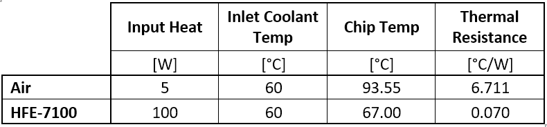
Table 1: Comparison of cooling performance between air and dielectric fluid HFE-7100.
It is clear that immersion cooling with phase change is a very effective means of cooling electronic components with the thermal resistance improving by nearly a factor of 100:1 for this particular example. However, in contrast to air, both thermal resistance and heat transfer coefficient (HTC) can no longer be considered constant but depend on the volume fraction (concentration) of the vapor phase. This will be discussed in more detail in the future.
Conclusion
Two-phase immersion cooling is a ‘cool’ technology with some compelling benefits. If you feel that immersion cooling might benefit your specific application, please contact us and schedule a meeting to determine how we could help! In most cases, a CFD simulation is a good first step to assess the performance potential of this approach as it applies to your situation.